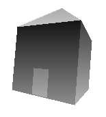
There are currently two tutorials: The first will show you how to create a simple house ('House.3D'), and the 2nd tutorial will show how to play around with the Draw3D 3D title ('Draw3D.3D').

The object you are going to create is a simple house that is 400 points wide. If you want to see the final product, open Draw3D, go into the File menu and click Open, then select the file 'House.3D', which should be in the current directory, otherwise you should change to the Draw3D directory.
You may be able to notice that it is basically a cube with a pyramid on top, as well as a rectangle for the door. One way to quickly create this house would be to open the cube in 'Cube.3D', so you can also load (open into same file) the pyramid in 'Pyramid.3D'. However, this tutorial will show you how to create it from scratch.
It is a good idea to have both this tutorial and Draw3D running at the same time, so that you can work through it. The first step is to obviously to open Draw3D, which has the filename 'Draw3D3.exe'. This will automatically create a new workspace, with your first vector (corner) created for you. To make the cube, you need to make 8 corners, and 6 faces between them.
Here are the first 4 vectors and the first polygon(face):
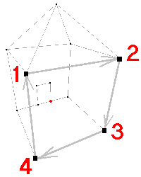
To make the next vector, you will have to create a new vector first. This is done by simply hitting 'Enter'. The new vector will always start at (0, 0, 0). First move your mouse to where it should go on the Top View (this sets how far back it is), and then where it should go on the Front View (this sets how high up, and far across, the point is). Looking at the diagram above, the second point should be at (400, 400, -400). Try setting this point yourself.
If you don't know how to, then you should read 'Using Draw3D'. This will explain the co-ordinate system. The important thing to remember is that you can use the Top view to set the X & Z co-ordinates, and the Front View to set the X & Y co-ordinates. Therefore, to set the point (400, 400, -400), you would place the mouse at (400, 0, -400) which is in the bottom-right coner of the Top View and press the left mouse button, then you place the mouse at (400, 400, -400) which is in the top-right corner of the Front View, and press the left mouse button. The reason that the Z coordinate stays -400 when you are setting the point in the Front View is because the Z coordinate of -400 is set in the Top View, and this stays as -400 when you are in the Front View.
If that didn't confuse you too much, then you can continue. The next vector is at (400, -400, -400). If you accidentally set a point in the wrong place then don't cry: Simply place it in the correct spot as if you haden't set it yet. You can even keep your finger on the left mouse button and drag the vector around. Dont forget to first add this new vector before you set it! Once you have set this vector, the next vector is at (-400, -400, -400). Once you have set this vector, you should have 4 vectors that look like two points from the Top View, but a square from the Front View.
This next step is difficult, so you should read the next two big paragraphs before doing what this tutorial says. Before you go on adding the rest of the vectors, you should create the first polygon. This is done by first creating a new polygon, just like you created new vectors, and setting each corner of the polygon to the vectors you just created. If you have already read 'Using Draw3D', then you should be aware that there are two different view modes: Vector (Wire-frame) mode, and Polygon (Solid) mode. When you first start Draw3D, you start in Vector mode, with the first vector already created, and pressing 'Enter' will create a new vector. To add a new polygon however, you need to change to polygon mode. This can be done by simply pressing the 'Escape' key. Once you are in polygon mode, pressing 'Enter' will add a new polygon, instead of a new vector. You should create a new polygon by pressing 'Enter', and you should verify that it was created by watching the bottom-right corner of the screen, where it should now say 'current polygon: 1 out of 1'. This means that you now you 1 polygon, and that the selected polygon is also the 1st polygon.
To set your polygon, you have to select each corner, and press the 'Spacebar', before continuing on to the next corner: You may have noticed that when you were placing the vectors that the current vector you were setting was coloured red, but the other vectors were black. This is because the vector you were currently working on was the current vector, which is coloured red vector. Creating a new vector changed the current vector. To use polygons, you have to take advantage of this. You can always change the vector to work on, by pressing the right mouse button when the mouse is above the vector. This lets you change previous vectors. When making polygons, pressing 'Spacebar' means that you want the next corner of the current polygon to be the current vector.
In other words, to make a polygon between the four vectors that you have created, you first change to polygon mode and create the polygon, if you haven't done so already. (You should now have a total of 1 polygon created). After you have created the new polygon, you can go back to vector mode, by simply pressing 'Escape'. Then move the mouse above vector 1 (in any of the 3 views), and press the right mouse button. This should select vector 1 as the current vector. (If you are having trouble selecting a vector, you can always hold down the right mouse button and move the mose around until you set the vector turn red). Now that the current vector is vector 1, press the 'Spacebar', to set vector 1 as the first corner of polygon 1. Now select vector 2 by moving the mouse onto vector 2 and pressing the right mouse button. Then press the 'Spacebar', to set vector 2 as the second corner of polygon 1. You should be able to see a line between vector 1 and vector 2. Do this as well for vector 3 & vector 4. You should now see a square between your four vectors. Here is a screenshot of what you should now have:
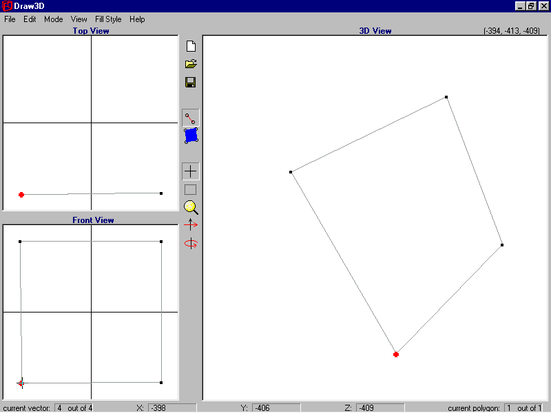
Now that you have made a complete polygon, you know basically everything there is to making entire 3D objects. However, there is much more left in to the house.
The next step is to create the next polygon and 4 vectors (polygon 2 and vectors 5 to 8). Here is a diagram of what you will now do:
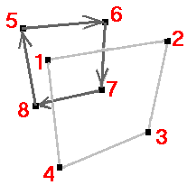
You have to do the same as for the first polygon, except with all the vectors' Z coordinates at 400, instead of -400. This will create another polygon as the first one, but further back.
This is done by creating and placing all the 4 four new vectors. You should try to place them onto the views without worrying about their actual coordinates, but by simply placing the 5th vector at the top of the Top View, so that it has a Z coordinate of about 400, and then place it again on top of vector 1 in the Front View. Also do this with vectors 6, 7 & 8.
If you had trouble doing this, then you can place the vectors the same way as for the first 4 vectors. Here are the coordinates for vectors 5 to 8:
By now you should have 8 vectors set out like a cube, but only one polygon. The next step shows how important it is to be familiar with the 3D View. Change to Polygon mode (by pressing 'Escape'), and create a new polygon (by pressing 'Enter'). You now have to select each new vector (vectors 5 to 8), and by pressing 'Spacebar', make the second polygon to between vectors 5 to 8. This is infact impossible to do in the Top or Front View, because there are often more than one point in the exact same position. It is accomplished by selecting the vectors from the 3D View. It may greatly help you in the 3D View, if you change to Rotate mode (by pressing 'R' or clicking the Rotate button on the toolbar or clicking Rotate mode in the Mode menu), and drag the left mouse button around the 3D View, so that the cube will rotate. (In Rotate Mode, vectors aren't visible, so you have to manually make them visible, by pressing Show Vectors in the View menu, or simply press 'F1'). It may take some time to get used to it, but try and rotate the object so that you know which vectors are closer to you and which ones are further away from you. If you are happy with the position, then change back into Edit mode (by pressing 'E' or clicking the Edit button on the toolbar or clicking Edit mode in the Mode menu), and then select vector 5, press 'Spacebar', then select vector 6, press 'Spacebar' again, and so on, until you have your second polygon. You should now have two visible polygons, which are on the edges of a cube. If your 3D View doesn't look like the diagram above, then you have done something wrong.
Note: As explained in the 'Using Draw3D' section, there are many other ways of setting & selecting points. If your vectors arent shaped as a cube as above, then you could go into the View menu and click Edit/View Vector co-ordinates. This will open a window that will allow you to type in the co-ordinates of the vectors. You could try that, and type in the coordinates given above for vectors 5 to 8.
More likely though, you have made your cube of vectors, but the polygons look wrong. You can also type these values in, under Edit/View Polygon co-ordinates in the View menu. For polygon 1, the vectors should be 1, 2, 3 & 4, respectively. For polygon 2, the vectors should be 5, 6, 7 & 8, respectively. If any of these values are different, type in the correct values.
The rest of the cube is a repeat of this step. Here is a diagram of the next step:
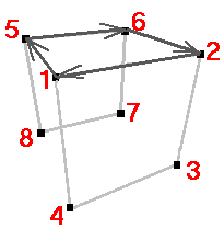
As you should be able to see from the diagram above, you dont need anymore vectors. All you have to do is add extra polygons to the existing vectors. You should be able to make the next polygon by yourself, as shown in the diagram. If you cant do it from the diagram, then here are polygon 3's corners:
Once you have your 3rd polygon finished, and it all looks like the diagram above, then you can continue to the next step. Here is the diagram of the next step:
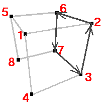
You should be getting the hang of things by now. Just in case, here are the 4th polygon's corners:
Here is the 5th polygon:
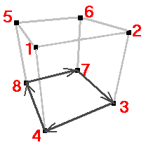
Just in case if you still need it:
Polygon 5's corners:
Here is the last polygon of the cube:
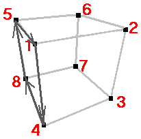
Just in case if you still need it!:
Polygon 6's corners:
Congratulations! You have hand made an entire cube! You can try rotating the 3D View around, so that you can make sure that everything went correctly. (Don't forget to press 'F1' to make the vectors visible). You should see a square in both the Top View, and the Front View, and you should have a total of 8 vectors and 6 polygons.
The next step for the house is to build the roof. The roof will need one extra vector as the point on top of the roof. Therefore, you have to create a new vector (make sure you are in Vector mode). Place this vector somewhere around (0, 490, 0). Note the Y coordinate of 490: This will make the vector fit within the Front View, but will still be higher than the rest of the cube.
Now you should add the polygons for the roof. Here is the first polygon:
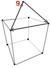
Notice that this polygon is only 3-sided, whereas all the other polygons where 4-sided. Draw3D has a limit of 4-sides for each polygon, but you can have as little sides you wish, because the unused sides can be the same as another side. For example, a triangle can be made by setting the last corner to be the same as the second last corner. Therefore, the triangle for the roof will be made as polygon 7:
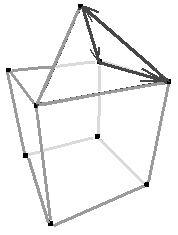
Here is polygon 8: the next triangle of the roof:
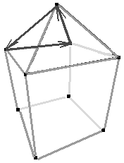
Here is polygon 9: the 3rd traingle of the roof:
Here is polygon 10: the last traingle of the roof:
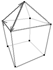
You now have the roof added to the object. But when looking at it, the roof isn't very high. You should press the left mouse button to set the roof's vector (vector 9) on the Front View, and while holding the left mouse button down, drag it higher up, until it is even off the Front View. Take it high enough that the 3D View looks more like a house than a cube (a Y coordinate of around 800 looks good).
Now all that is left is the door! The door is thin enought that it can be done by just 4 vectors and a polygon. Here is what it will look like:
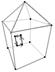
The vectors are as follows:
Polygon 11 vectors:
Congratulations!! You have (should have) completed the House!
Here is your house!
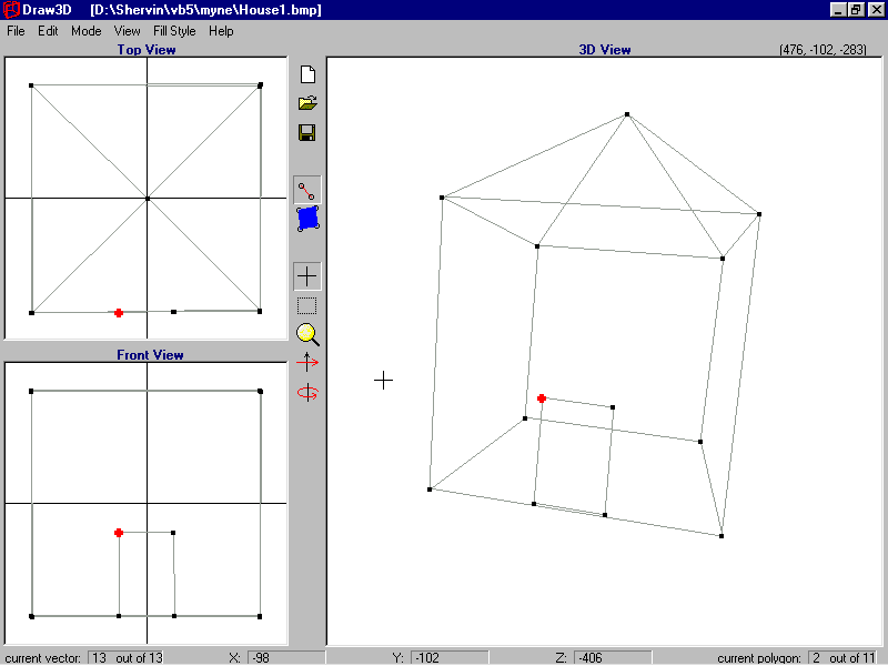
Note: If you look at your new version of the House, compared to the file 'House.3D', they should look exactly the same, and yet your one uses a lot less of vectors and polygons. This is because the other one was made by simply loading a complete cube & a complete pyramid together, and so some vectors were duplicated. This can be fixed by Remove Unused Vectors in the Edit menu.
Click here to go to the second (much easier!) tutorial:
Tutorial 2: 'Draw3D.3D'
If you have any trouble with Draw3D, or any comments or ideas, you can e-mail me.
by Shervin Emami, gorbash@optusnet.com.au