
(Last updated this top bit and last bit on 14, March, 1999, but all tutorial stuff is all old)
If you saw that I said to come back for the new version with 3D glasses, then sorry, because I didn't finish it. The 3D glasses effect doesn't work as well as I hoped, and it gives you a headache.
The new version (not yet available) has many new features, including the fact that it works with AutoCAD '.DXF' files as well as Draw3D '.3D' files. (Not to mention that it seriously displays the 3D view about 1000 times faster!)
Note: It seems that the file to download below is the wrong file, and I accidentally deleted the correct file!. You may need Visual Basic 5.0 with Windows 95, to run the program. The new version should be ready by about April 99, which shouldn't have as many problems, and won't need Visual Basic. I am also making a DOS version.
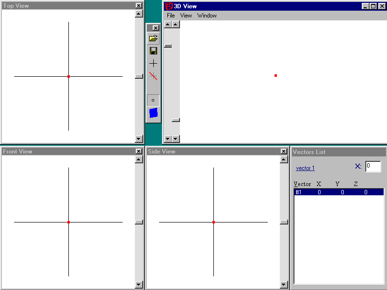
The following is a screen shot of the Draw3D windows:

The three similiar windows on the left and bottom are the two-dimensional views. That is where you plot your points, also called vectors. The top-right window is the three-dimensional view of the object, using the co-ordinates that you plotted. Each two-dimensional view also has a vertical scroll-bar, which you may use to rotate the three-dimensional object in real-time. The cross-hairs show the centre of the rotations, so that may be used as the centre of your object.
A simple 3D object to get started on is a line. When you first start the program, there is already a vector in the centre of each view, which is location (0,0,0). When you click the left mouse button on any two-dimensional view, the point will move to the new location, and the 3 other views will move their point as well, based on your new co-ordinate.
Place the point somewhere in the view. Once you have the first vector, the next is needed. You can obtain another vector by pressing the ENTER button on the keyboard. A new point will be placed at the origin (0,0,0). You can move that point to any two-dimensional destination you wish, just like you did for the first point. Once you have created two points, you should be able to see two points on each view, including the three-dimensional view. Use the vertical scrollbars on the two-dimensional views to rotate the three-dimensional points, until you can understand how they are rotated.
Between the 2 top windows is a toolbar window in the centre. That toolbar has the obvious Open & Save buttons, but also some other buttons. It is sub-divided into two areas, the menubar and the vectorbar. The menubar is the top part, with the Open & Save and two other buttons. The vectorbar is the lower section, consisting of two buttons: a point and a polygon. The point is currently selected, meaning you are in vector mode. If you click it again, it also creates a new vector, just like pressing ENTER. Clicking on the polygon button changes you into polygon mode. In polygon mode, you can't move or edit vectors. Polygon mode is used to view 3D objects with sides, instead of simple line drawings, as used in vector mode. Click on the polygon mode button to bring you into polygon mode. You will notice the three-dimensional view turn black. Click the button again to create a new polygon. The final window on the bottom-right is a list of all the vectors, when you are in vector mode, or all the polygons when you are in polygon mode. It should now be saying '#1 1 1 1 1". Click the vector mode button to go back into vector mode. This should change everything back how it was. Now that you have two points and a polygon, you can create a line. Right-click on one of the two points, to select it. Make sure it turns red, meaning it is selected. Press the space-bar. This will tell the program that it is the first part of a polygon. Next, right-click on the other point, and press the space-bar. There should now be a visible line between the two points on all views. You can rotate the three-dimensional view and it will rotate the line as well as the points. This is how it all works. The line is stored as each corner being a vector number. If you move that vector, the line will also move.
You now can see a 3D line, which is actually a 4 sided polygon, but with three corners being the same place. You can make a triangle using 3 different vectors and a 4 sided polygon using 4 vectors. Create two more vectors by pressing ENTER twice while in vector mode. Whether you decide to add new vectors by pressing ENTER or by clicking the vector button on the toolbar is personal choice, but if you press the button on the toolbar, make sure you hear a click, because sometimes, the click will pass unnoticed. Move your 2 new vectors to different places. Select one of the vectors by right-clicking it, and press the space-bar. The 3D lines should all change to a 3D triangle, now that you have 3 vectors. Select the last vector and press space-bar on that, and you will have a complete three-dimensional, four sided polygon which you can modify easily. You may rotate it, and once again, moving one of the vector's will also modify the polygons using it. You can see which side is about to be created for the polygon, by looking at the tiny number on top of the toolbar. If you selected the wrong vector, you may press F4 to decide which side you want to select. You may also choose that function by going through the menu under View: Set Polygon Side.
You now know how to create entire polygons, and this can be repeated as many times as you wish (actually, only 32767 polygons are allowed at a time). The more polygons or vectors you have the slower it moves, so try not to waste them. You may delete vectors and polygons by clicking DELETE, or BACKSPACE. Each time you delete a vector, many other vector numbers will change, to be shifted into that place.
The rest of the program's features are for helping you make and view your 3D polygons, that may add to a great looking picture. The menu has most of the functions available, but there are a few other hidden features. You are already familiar with some of the toolbar buttons. You know how to change between vector and polygon mode. If you click on the same mode button twice or more, it will add a vector or polygon, depending on the mode. The toolbar also has a button with a plus symbol, which also adds a new vector or polygon, and the button with a cross through the plus symbol deletes the current vector that is selected, or it deletes the last polygon. This is an important note: Whenever deleting a polygon, remember that the last polygon will be deleted, compared to deleting vectors, where the current selected vector is deleted.
The y-axis is vertical on the Front View and vertical on the Side View. The values move -500 upto +500 from bottom to top.
The z-axis is vertical on the Top View but horizontal on the Side View. the values move -500 upto +500 from top to bottom on the Top View and right to left on the Side View, meaning that the Side View is actually the Right Side View of the 3D object.
The vectors list has some other functions as well, for editing your vectors. For example, if you click on the Y-coordinate of the 9th vector in the list, the 9th vector will be selected for editing, and the name 'vector 9' will appear in the list window, and 'Y' will appear next to the text-box, which will contain the value of the y-coordinate of the 9th vector. You may type in it's new number for manual data entering. The values should be between -500 and +500, with 0 being the centre, -500 being at the start of the 2D views, and 500 being on the end of the view. You may also enter values as far as 800, but you won't be able to see them on the 2D views. Pressing ENTER will enter the value typed into that coordinate of that vector. You can press up or down to change the vector that you are editing, and pressing CTRL left or CTRL right will change the axis coordinate. For example, pressing CTRL and left will change from the Y-axis to the X-axis. You can press TAB to shift through the different windows in a clock-wise direction, but to change from the 3D View, you may have to press something else such as left key to move to the list window.
The 2D views each have rotation bars, and the value of the angle will be displayed on each title bar. The vertical scroll-bars on the 3D view aren't rotation bars. The left bar is a sizing bar, which controls how big the 3D View is. The right bar controls the perspective ratio for the 3D view. The higher the scroll is, the higher the perspective is. High perspective usually doesn't look too well, but is available if you want to try it. You can turn perspective off through the menu under View : Perspective, and changing the perspective scrollbar will automatically turn it back on if it was switched off.
Click here to Download Draw3D.zip (206kb)
Click here to Download some basic sample 3D files that I have made using Draw3D (2kb)
If you make any 3D objects, you can e-mail me the file (preferably the *.3D file, but *.bmp is better than nothing) and when I have enough, I will add a contributions page, showing everyones 3D objects, including all of myne.
by Shervin Emami, shinab@eisa.net.au